
 Alignment
Suspension
There is a temptation to regard suspension as a topic ruled by something akin to "black magic", a subject so arcane as to require years of study and secret knowledge to fully comprehend. In actuality, understanding suspension is really very simple - the complexities arrive later when we start discussing weigh transfer and roll centres and whatnot.
At its most basic, the role of the suspension is to allow the wheels to conform as much as possible to road irregularities while isolating the body of the car - the sprung mass - from the effects of transiting these irregularities. This it does to varying degrees of effect; no suspension can ever completely isolate the sprung mass. That being said, the sprung mass has very much more inertia than the components of the unsprung mass (the wheels, tires, brake rotors/calipers, and a portion of the mass of the shocks, springs, and connecting arms) so the sprung mass tends to follow a much smoother path than do the individual wheels.
As a direct result, the sprung mass is subject to forces which can cause it to move as a unit relative to the unsprung mass. Much as the unsprung mass moves up and down in reaction to bumps, the sprung mass moves around in reaction to accelerations - things like turning, braking, and so on.
The primary movements we are concerned with are pitch (a dive/climb rotation) and roll (a left/right rotation)
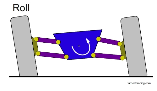
Of the two, roll is the most important from a cornering perspective, as that is the primary sprung mass (chassis from now on) movement during cornering.
As the chassis rolls from zero roll at the entry phase of the corner, to maximum roll at midphase (or near it), and then back out to zero roll at corner exit, a number of things happen:
- The shocks compress, then uncompress;
- The springs compress, then uncompress;
- The sway bars (if any) twist then untwist;
- The bushings at the pivot points of the suspension control arms deform; and
- The wheel and tire move through an arc defined by the layout of the suspension control arms.
The primary goal of the suspension, from a racing point of view, is to do all these things in such a manner as to maximize the amount of time that the tire spends in its "happy place" where it is making maximum grip. A secondary goal is to perhaps induce behaviour conducive to balancing the car or affecting responsiveness - things like toe and roll steer come into play here. But for the time being, we'll limit discussion to the primary goal.
The first (and most important) consideration is that no suspension can "create" grip. The maximum amount of grip is produced when all four tires are equally loaded and in their "happy place" from a temperature, pressure, camber, and slip angle point of view. That's the best you can do. Suspension tuning can "unlock" potential grip, and a poorly tuned suspension can indeed lock away a lot of grip, but a happy tire is a happy tire.
Secondly, the factors that dictate what constitutes a "well-tuned" suspension are mostly related to the tire. A tire that is insensitive to camber angles is not going to require strict control over dynamic camber. A tire whose load curve falls off very slowly will be tolerant of changes in weight transfer, and so on. The factors remaining tend to be environmental, particularly how bumpy the race surface is and the nature of the course layout.
Thirdly, the basic design of the suspension we use (assuming a production-based car as I do) is largely determined by the original manufacturer - and they may have had goals in mind other than maximum lateral grip. For an OEM, packaging (fitting the suspension in a small space) ride quality (both passenger comfort and NVH (noise, vibration, harshness)), and cost tend to be higher up the food chain than pure performance.
But whatever type of suspension the car is equipped with, that is likely the type of suspension you are going to race with. The rule book, the highly integrated nature of unibody construction, and economics makes it very difficult to switch from (say) a MacPhearson strut to a Double-A Arm.
Accordingly, the first step in improving a suspension for race use is to figure out what the current one is doing. This is so important, relatively easy, and reasonably cheap and yet almost nobody does it because it looks scary and hard. Instead, everybody wants to rush in to buying shiny parts and starting the Great Cut and Try Cycle.
Measuring and modelling the OEM suspension saves enormous amounts of time, energy, and money, and can give you an initial setup that is most of the way there right out of the box. Time spent measuring is seldom wasted.
Modelling the Car
The steps involved in modelling the car are as follows:
- Measure the key components of the suspension and transfer the data into a modelling program like WinGeo.
I particularly like WinGeo because its data collection procedure is very simple and straightforward (it's NASCAR-proof). Example of how it is done here.
This process will give you camber curves (both bump and roll), caster, bump steer, motion ratios, and roll centres. It will also allow you to play with the car, rolling and pitching
it and whatnot, and see firsthand what all the components are doing. If you spring for the top-dollar version, you can even play back the data from your wheel position
sensors through it and watch your suspension react to real-world data (which is awesome for validating the numerical model);

- Weigh the car and get corner weights. Weigh the unsprung masses too;
- Measure the Center of Gravity height. This one is annoying because it involves lifting one end of the car up in the air while the other end is on the scales. If you have a Formula Ford, it is pretty easy. For production-based cars, it takes a little more ingenuity. Having access to a lift or forklift helps, but there's more than one way to skin that cat.
- Dyno the shocks and springs. Shocks are complicated enough to deserve their own chapter; and
- Measure the sway bars.
With all this information, you can now plug values into the Dynamics Calculator and start to get an idea of what is going on.
Because the grip level of race tires is so much higher than street tires, usually the next step is to pick springs.
Spring Selection
A spring change to a stiffer spring limits the amount of motion that the suspension undergoes in reaction to a particular acceleration (so does a change in CG height and track/wheelbase, but those are much harder to change than springs and for most practical purposes less effective too)
But there are upper limits on how stiff we can go with the springs, so we need a measure of "stiffness" to set the boundaries.
That number is the natural frequency of the suspension - it is worked out for you in the Dynamics Calculator. Rule of thumb is rear NF slightly higher than front (by a tenth of a Hz or two - it keeps the sprung mass from pitching too much because the front wheels encounter bumps first so the rear needs to react a little faster) Street car: 0.8 Hz. Occasional autocrosser: 1-1.5 Hz. Full-bore autocrosser: 2.2-2.5 Hz.
Yes, it really is that simple. Measure your corner weights, unsprung masses, and motion ratios, and then pick springs that put the front NF at 2.2 Hz and the rear at 2.5 Hz.
Of all the claims I've made in this book, this is probably the one that caused the most serious discussion. It's also the one that is the hardest to justify, given that it is a bit of a "magic number" and tire and surface dependant at that. For a slicker or bumpier surface, it could probably drop a tenth of a Hz or so. Grippier tires (like slicks - although sidewall stiffness will play a part here) might jack it up a little. The point here isn't if the car should be 2.2000 Hz or 2.201324 Hz - the major takeaway is that ~2.2 Hz is the ballpark. If the natural frequencies on your Camaro work out to 1.7 Hz front and 3.9 Hz rear... well, you've got a problem there Skippy. (A car like this should be undrivable, all loosey-goosey-can't-put-power-down - unless the front shocks have massive amounts of rebound to compensate....)
Note too that, very much unlike spring rates, natural frequencies CAN be compared car-to-car. A 96 Camaro with a coaxial McStrut (motion ratio ~ .98) running a 700lb spring has a similar natural frequency to a 96 Mustang with an A-Arm mounted spring (motion ratio ~ .4) and a 1600lb spring. Way different spring rates, nearly identical natural frequencies.
While we're on the topic of "picking springs", I am of the opinion that there is only one spring provider worth a damn - Hypercoil. Of all the springs I have tested - you need a spring tester, MK Technologies makes a good one (and Hoosier Tom will sell it to you) - the only springs that reliably tested in spec were the Hypercoils. The worst offenders were the no-name purple springs that come on JICs; I saw 25% variation on some of these.
Just like shocks you must test your springs, and do so regularly. The spec on a Hypercoil is 3%, and at stiffer rates, it is possible to try and add 50lbs of rate, but swap in a spring on the soft side of the spec for a spring on the stiff side of the spec, and effectively do nothing except fool yourself. TEST TEST TEST! Unlike shocks, no spring vendor is going to provide test results for individual springs, so you get to buy a spring tester. Tell Marty and Tom I said "Hi".
I'm also a huge fan of using standard 2.5" or 2.25" springs in a coilover configuration whenever possible. Not only does this package beautifully, it gives you access to a huge, fine-grained range of spring rates to choose from. A Hypercoil 2.25" spring is THE quality bang for the buck deal in racing; they could be charging well in excess of what they do. Not only that, a coaxial coilover configuration means the springs and shocks have the same motion ratio, which makes the NF calculations a little bit easier.
If you can, use the smaller 2.25" springs - they are a little bit lighter and give a touch more clearance around the shock.
Incidentally, there is no advantage whatsoever to threaded body shocks (sometimes called "real coilovers" by the Ricers) over threaded sleeves. If anything, divorcing the spring perch threads from the shock means the sleeve can be sacrificial and there's less risk of trashing an expensive shock body when something damages the threads.
Weight Transfer and Geometry
With the springs chosen to set the NF where you think it needs to be, now you can start looking at weight transfer.
Weight transfer is a complicated subject that is covered in its own chapter. In addition, the Dynamics Calculator works it out for you. By tuning the sway bars, you can adjust the weight transfer front and rear percentages (which affect balance) and you can determine total roll angle.
Total roll angle gives you the final piece of the puzzle, as now you can feed this back into WinGeo to see the suspension operating envelope. With this in hand, you can set initial camber angle (to generate the amount of dynamic camber the tires want) and you can check for bump steer/roll steer and correct it., Lower the suspension as much as you can while keeping the curves sane (don't forget to put the lower CG into the calculator and see how that changes things), and if you have to trade a higher CG for better camber curves, go with the better camber curves unless the tire is insensitive to camber.
You can iterate around with the model and get a feel for how changing different parameters changes the suspension curves (in WinGeo) and weight transfer (in the calculator). You'll probably find that there's a "sweet spot" in the suspension design where you can roll around a bit with little to no change in dynamic camber and minimal bump steer - that's a good spot to be.
Incidentally, the first time I modelled a C5 Corvette, it was amazing to see all the curves line up on a "sweet spot" on a ride height 1" lower than the OEM height. It's like the GM engineers know what they are doing....
Other Considerations
That's all good - on paper. If you work it out this way, you get a very decent first kick at the cat. Reasonable natural frequencies, dynamic camber under control from max left roll to max right roll, weight transfer balanced to match the static weight distribution, no bump steer from max left roll to max right roll - this should be a car with very happy tires and no bad habits. Balance will probably need tweaking but the car should be immediately very quick.
As you gather data, you can start cross-referencing live data against the model and make sure everything lines up. If it doesn't, there's a flaw in the model and it needs to be hunted down.
There are, however, a few other considerations to take care of:
Suspension Bearings
The first is that the OEMs tend to use rubber as a suspension pivot or bushing material. This is used to offset NVH, as rubber damps out high frequencies very effectively. But once we start feeding race-tire-levels of lateral G through those bushings, they aren't going to behave very well. They will squirm and wiggle around, and may eventually tear. This is bad.
The more force you generate through the tires, the bigger a deal this is. On a street car, you replace any single-axis bushing with poly or nylon, keep the springs coaxial, and call it a day.
Beware that "single-axis"! A bearing that needs to pivot on multiple axis - like the 2G DSM front shock fork and upper shock mount - cannot be replaced with poly!
As the grip goes higher, you need something stiffer than poly, so you do high-quality, Teflon-lined spherical bearings in every pivot point. At still higher grip levels, you start looking at control arm flex and especially chassis flex, and get rid of it as best you can.
Spherical bearings are your friends; the amount of improvement that comes with eliminating rubber can be really surprising. Note, however, that there are different grades of spherical bearing, and there is a significant quality difference, for not that big a difference in individual cost. A wide, Teflon-lined, precision-grade bearing is what you want - I used Auroras for the most part. Get the Aurora catalogue; it does a really good job of teaching the engineering required to design parts using spherical bearings.
Note that there is a very large difference between the strength of the bearing loaded axially (like at the top of a shock) and radially (like in a suspension pivot). An axial load takes a much larger bearing than a radial load.
As far as installing bearings goes, pick a bearing from the catalogue, machine out the part to an interference fit (per the specs in the catalogue) - I usually machined out to a shoulder - and retain it with a snap ring for extra insurance. Then you get to make the adaptor sleeves that neck down the bearing ID to the OD of the pivot bolt, and widen the unit up to the width of the attachment clevis.
It can be handy to own a small lathe....
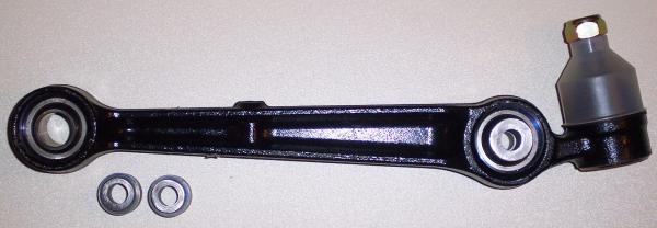
While you're at it, it can be worthwhile to install Torrington bearings in the spring perches:
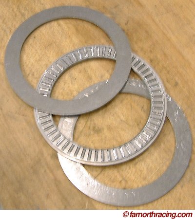
This gets rid of some stiction at the spring/seat interface (the spring twists as it compresses) and as an added bonus, makes adjusting ride height like 1000% easier. Happily, all you need are two races (the flat plates) and one bearing per spring - no machining required.
At one point, I was putting them on both ends of the spring, but that turns out to be overkill - just one end works fine.
For the ultimate solution, Hypercoil makes floating hydraulic spring seats, but they are pretty expensive and a Torrington bearing with a proper coaxial spring perch gets you most of the way there.
At some point, chassis flex starts becoming a significant portion of total suspension movement and until you get rid of that flex further suspension tuning is going to be relatively ineffective. This was a key part of the concept behind Street Modified's "don't touch the chassis" rules and it is surprisingly effective. Look at any high-dollar race series and see how much effort goes into stiffening the chassis....
Coaxial Spring Mounts
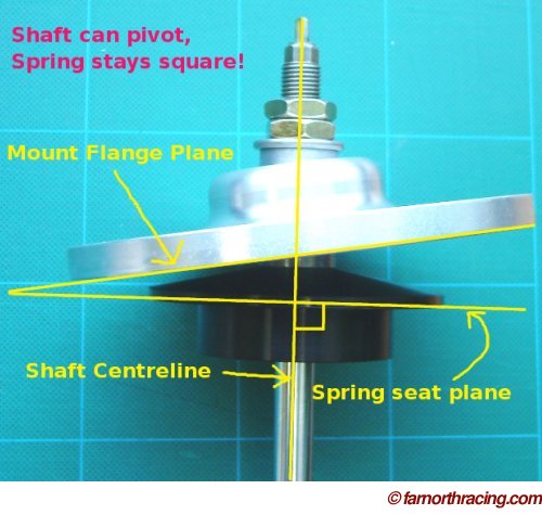
Any coilover absolutely must keep the spring coaxial to the shock. Any bending moment on the shock rod and spring that occurs when the spring seat doesn't pivot coaxial to the shock rod wears out seals in a hurry, can bend the shock rod, and worst of all, does all kinds of funky things to the spring rates, as the spring is no longer compressed evenly throughout the shock stroke. It is really, really worth the effort to ensure the spring is always compressed squarely.
Most aftermarket suspension providers have figured this out, and even the crappy Japanese and Chinese stuff (JIC, TIEN, etc) comes with coaxial spring perches these days. Some legacy parts (Ground Control in particular) continue to used fixed spring perches, and these should be removed from the car and thrown away with great enthusiasm.
For some ideas on how to do this properly, see this page.
I've been asked for clarification as to exactly what I mean by "fixed spring perches":
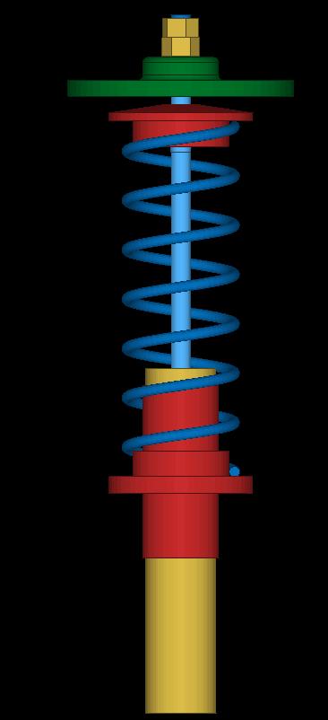
The following is a set of Ground Control upper spring mounts for a second generation Eagle Talon/Mitsubishi Eclipse, sold to me by Jay Morris of Ground Control in late 1998 or early 1999 as I was prepping the car to move to E Street Prepared. These were an option to a set of shocks and springs (Konis and the GC-designed coilover sleeves, using standard Eibach 2.5" OD springs).
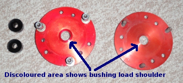
This is the top view. The black cylinders on the left are a hard plastic (or perhaps polyurethane) bushing that secures the top of the shock shaft to the upper mount by sandwiching the mount plate between two bushings - you can see where they fitted from the discoloration of the upper mount anodizing. These bushings are extremely firm.
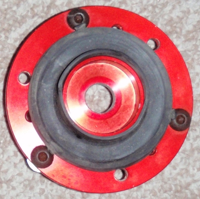
This is the underside of one of the mounts. The rubber pad is where the top of the spring sits. Also visible is the discoloured area from the bearing surface of the lower half of the bushing sandwich.
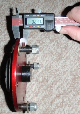
This shows how the whole thing fits together, and how thick the plate is. By way of comparison, the mount in the top photo, also for a 2G DSM, is 0.375" thick at the edges, and 1" thick surrounding the bearing.
As you can see, the Ground Control assembly does not allow for any articulation between the shock shaft and the upper plate whatsoever, nor does it keep the coaxial spring square to the direction of compression. What is perhaps a little tougher to see is that both plates (which were on the car for a full season) are seriously bent. The 2G DSM front suspension articulates at this joint on the order of some 15 degrees just by turning the steering wheel lock-to-lock (never mind bump articulation, which it does too) and notwithstanding the hard poly bushings, it DID articulate with this plate installed - by virtue of distorting the upper mount and bushings and bending the spring.
Not to mention that all shock loads passed directly through that little shoulder on the plate, which did a fine imitation of a Belleville washer spring (like a clutch flex plate).
All told, this mixture of resisting movement where it needed to articulate, and allowing movement (flex) where it needed to be stiff, makes this part pretty much the poster child for how not to design an upper spring/shock mount. The following season saw the upper mounts replaced with articulated mounts with a pivoting spring seat, and suspension performance improved rather spectacularly.
This particular crappy design is not limited to Ground Control. Many, many cheap coilover kits rely on a similar design, because it is cheap to make and easy to install. To bad it doesn't work.
(Ground Control advises me that they do make properly articulated mounts for "racers". That may be so; I have no particular beef with Ground Control per sae, only with this design of upper spring mount - their coilover sleeves are actually pretty good. But if they (or anybody else) try and sell you something like this thing, take your business elsewhere.)
Summing Up Suspension
So then, here's the sequence:
- Replace all the rubber suspension bushings with spherical bearings;
- Measure and model the suspension to get:
- Motion ratios (and directly measure these to confirm the model);
- Unsprung weights;
- Sprung weights;
- Natural Frequencies;
- CG Height;
- Camber curves in roll and bump; and
- Bump Steer in roll and bump;
- Pick springs to set the natural frequencies where you want them;
- Set ride height as low as possible given camber curves and tire clearance;
- Fix bump steer;
- Go testing;
- Input your test results back into the model; and
- Tweak suspension settings to get your tires happy and the car balanced.
Learned something?
Help keep ATW online!


