Suspension Modeling Project
Two very important things happened at Nationals 2002.
The first was that immediately after winning a ProSolo Championship, on the same surface, and in similar conditions, the car changed from a winner to a spinning, undriveable pig.
The second was that Carroll Smith gave a tech seminar at the site where we were able to bombard him with questions for the better part of four hours.
Out of both of these events came the conviction that we simply didn't understand enough about the way the suspension on the car worked, and that if we wanted to keep on winning, that had better get addressed before next season.
Carroll insisted that a large part of that process was making an accurate kinematic model of the suspension, and he recommended using WinGeo3, produced by Bill Mitchell Software. Who am I to argue with the author of Tune to Win?
So we bit the bullet, bought the software, and started making the model.
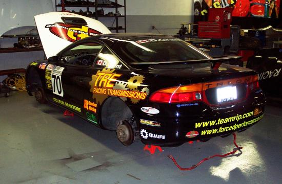
The poor innocent victim, awaiting measuring.
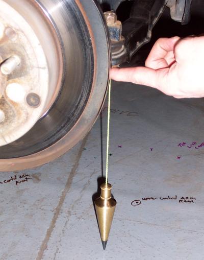
Measuring the car involves projecting the location of all the suspension pivot points onto a plastic sheet, using a plumb bob. Here is a point on the rear suspension being plotted.
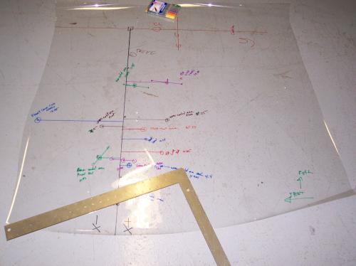
The finished projection of the rear suspension, after plotting the axis and measuring all the points. From this comes a list of points in 3-space which the software uses to form the model.

And here's the model of the rear suspension. It can be moved through its entire range of motion, and all the relevant data examined.
Like this - a plot of steer vs suspension travel. It can be seen here that the suspension toes in in both bump and droop.
2010 Update: This wound up being one of the most important things we ever did with the car. Out of this project leads the path to fully 80% of the material in Autocross to Win. I am utterly convinced that this needs to be the first step in building a race car.
I measured probably a dozen other cars, and learned a few tricks along the way:
- Rather that the string plumb bob pictured, I switched to a laser plumb bob. This makes transferring points to the plastic SO much faster, as you don't have to wait for the stupid bob to stabilize. Plus you can be very precise with the laser, reaching points that can be difficult to pick up with the string;
- Strictly speaking, the transfer surface need not be plastic - it can be paper. I had access to the plastic and it takes Staedler markers well, so that's what I used;
- You need a long straight edge to do the marking - a brand new (ie, undinged) carpenter's level works well.
- For measuring the distances on the paper, I used a digital caliper. These things have gotten very, very cheap and they are invaluable; and
- For measuring heights, I tried using a digital height finder, but often it wouldn't fit. So I fabricated a couple of telescopic pointers, in a couple of different lengths, and used that - you adjust the pointer length until it spans the distance between the measured point and the floor, and then you measure its length with the digital caliper. You could also use something like an old walkie-talkie antenna, or a telescopic magnet, or what have you.
After you've done the first one, it only takes an hour or two to measure a whole car. It looks like a big ordeal, but it is not.
