Custom Aluminum Intercooler Piping
The intercooler piping on the stock engine is perhaps a touch too narrow for the power levels I will be making. As well, the OEM piping uses rubber hoses at interconnects and hoses are the tools of the devil - I much prefer Adel Wiggins quick-disconnects or similar O-ring based sealing solutions.
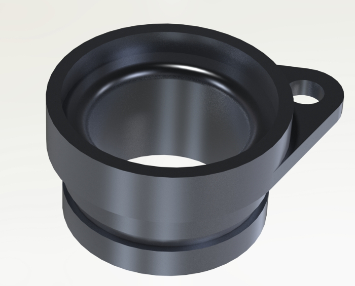
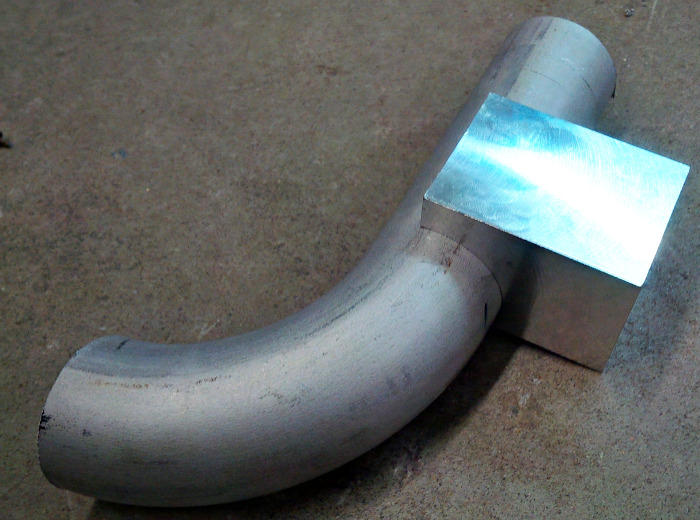
The OEM rear turbo outlet pipe actually uses an O-ring based sealing solution that I really like, so we start there. Machine an O-ring bung for that rear turbo that we can weld on to a chunk of mandrel-bent aluminum tubing, then weld up a replacement pipe made out of sectioned mandrel-bent U-bends. Include provisions to fit the OEM heat shield and the OEM bolt attachments to keep the pipe supported and rigid.
Strictly speaking, this project isn't really necessary, but it is good practice developing fabrication skills needed for later projects.
We start with the bung itself:
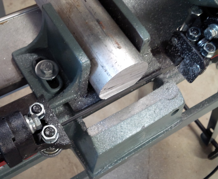
First we cut off a chunk of round stock on the saw
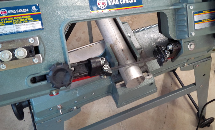
A few minutes later, all done! Soooo much better than using a Sawzall or a manual hacksaw.
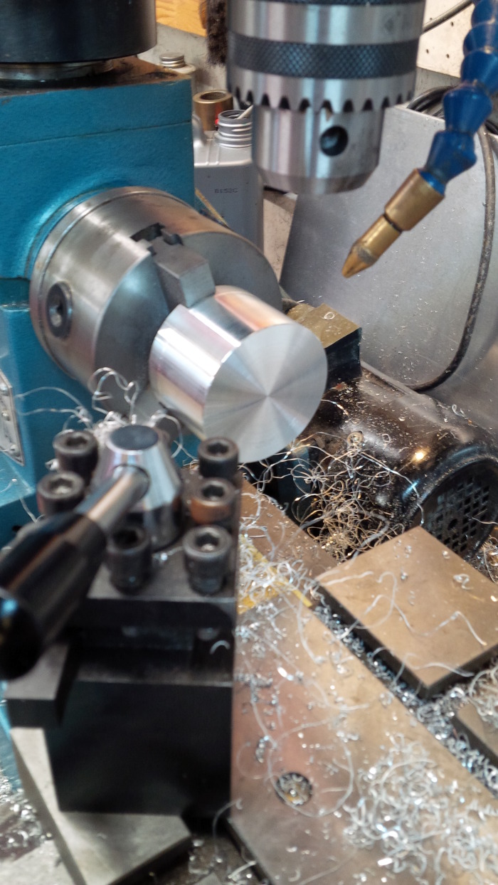
From here, into the lathe to get faced and dressed.
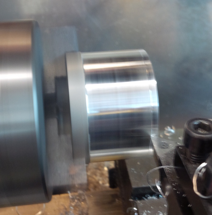
Ready to have the centre bore punched out and the outside profile turned town.
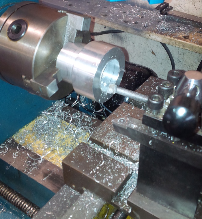
Drills can only take you so far - the majority of the stock removal is done with a boring bar. These 3/8 carbide bars turned out to be too flexy and too dull for aluminum, so I stepped up to a 5/8" indexible bar with an aluminum-specific insert. Much faster, no chatter, and a better surface finish too.
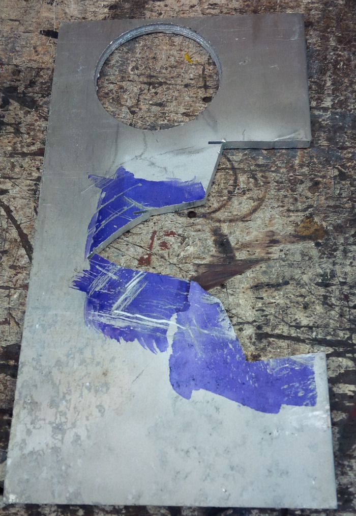
The next step was fabricating the hold down tab and welding it on. Use a hole saw in some plate to get the radius, then cut the tabs out with a jigsaw. I got three tabs out of the first hole.
No images of the welding, because I don't want any evidence of what those welds looked like prior to machining. Good penetration is all I can say about them.
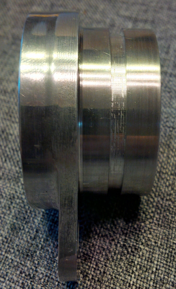
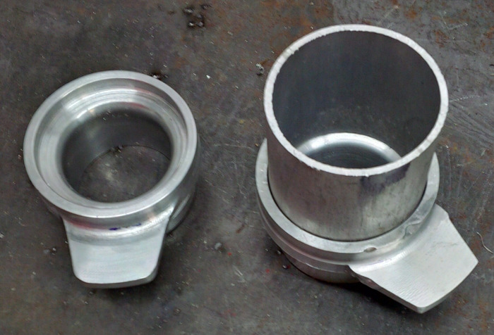
With the weld done, back on the lathe to dress the welds and finish the bores. The top join gets a radius for strength, but the bottom side stays a sharp corner so it fits flush on the turbo housing. The step between the turbo outlet bore and the pipe OD gets a radius (like a velocity horn) to help smooth the transition from the smaller OD to the larger one. Even better would be a lofted transition from the one diameter to the other, but that's a PITA to machine on my lathe. It could be done easily on a CNC mill though.
The next step is the O Ring groove. These need to be cut to a specific width with a fairly tight tolerence. Happily, there are people who specialize in this sort of thing.
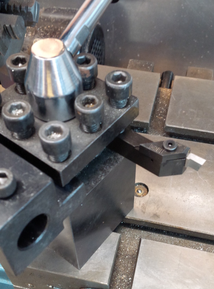
This is a Thinbit tool from Kaiser tool company. They make indexible tooling for cutting grooves.
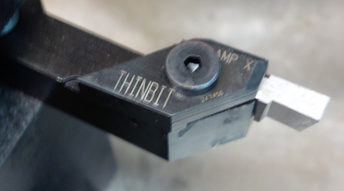
They can produce inserts in HSS or carbide to whatever sizes you want. This groove needed to be 0.142", so they sent me an insert that cuts exactly that size.
And as expected, it worked perfectly.
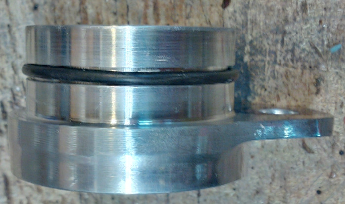
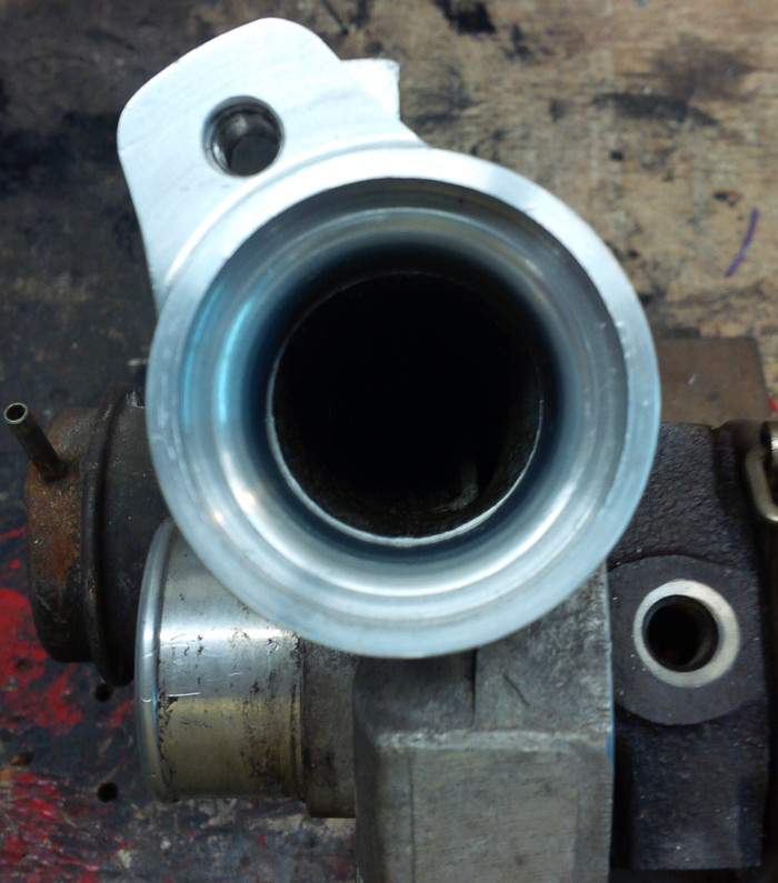
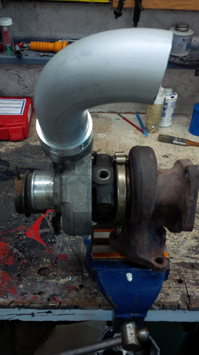
Test fit on the turbo fit perfectly - the turbo outlet isn't perfectly on centre, but that is near enough to make no nevermind, and the o-ring fits nice and snug.
Test fit on a U-bend looks good too!
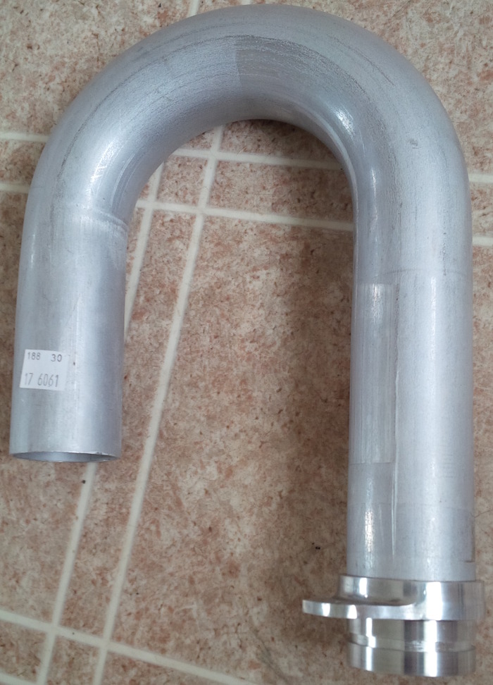
And now fabrication of the pipe itself can start.
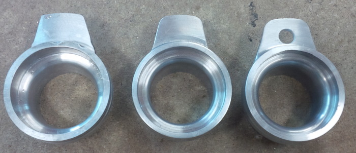
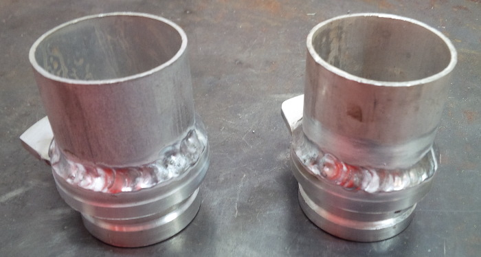
Here are the three prototypes, ending in the "production" part on the right. Much was learned in the process of making these and quality is up while manufacturing time is down. And the first two provide raw materials for welding practice.
Now time to start practice welds:
Not perfect, but better than when I started out at least.
Something else we need on this pipe are a series of standoffs. Two hold the turbo heatshield, and the other secures the piping to the intake manifold. Far too often, aftermarket pipes omit these kinds of details, because working them out properly is hard to do and expensive to incorporate. I, on the other hand, am my own labour, and I have a fetish for doing things properly. So we add the standoffs.
The first step is to fabricate a jig that picks up the locations of the standoffs from the OEM pipe:
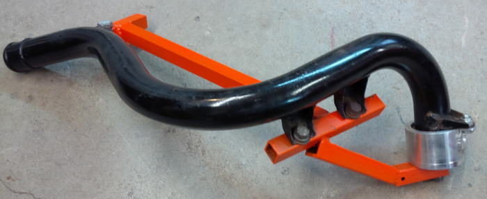
As is tradition, the jig is painted bright orange so it doesn't get mistaken for scrap and thrown out. Most of it is 3/4" steel tubing MIG welded together. The turbo outlet socket is aluminum bored out on the lathe and a bolt tab welded on.
You can see the three standoffs that have to be fabricated - two up front, and one behind. Because the pipe is aluminum, so too must be the standoffs, so we will machine them from billet.
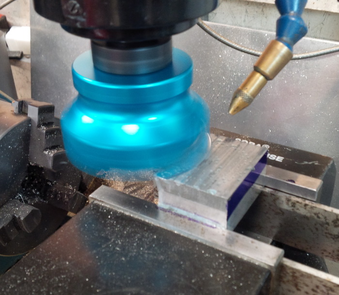
Because I don't have a CNC mill yet, that poses a challenge - cutting the radius that mates with the OD of the pipe. We want lots of surface area to spread the load and the match with the pipe needs to be pretty exact.
There's a tool for that - the annular cutter (also known by the trade name Rotobroach). The bastard child of an end mill and a hole saw, this cutter chews away a ring (or annulus if you want the technical term). It is much, much more accurate than a hole saw, doesn't need a pilot hole, takes less power to drive than a drill of comparable size, keeps the plug for future use (instead of converting that entire volume to chips) and is suprisingly cheap. The only real downside is that is uses an oddball Weldon shank holder (that uses different dimentions than a Weldon shank end mill holder, of course) so you have to either buy or make one to use them.
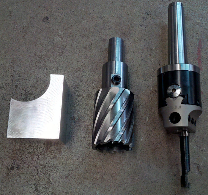
I chose to make one, at least for now. The runout is a little high... someday I'm going to have to upgrade my lathe.
I bought one slightly undersize, with the idea being that I would finish bore it with the boring bar and clean it up. That turned out to be completely unecessessary, as the size and finish wound up being dead on. I'm going to get a bunch of these suckers; they will be great for fishmouthing tubing.
With the radius cut, now I had to divide the block up into the roughed-out standoffs. My new horizontal bandsaw came with a vertical table attachment, so let's give that a try:
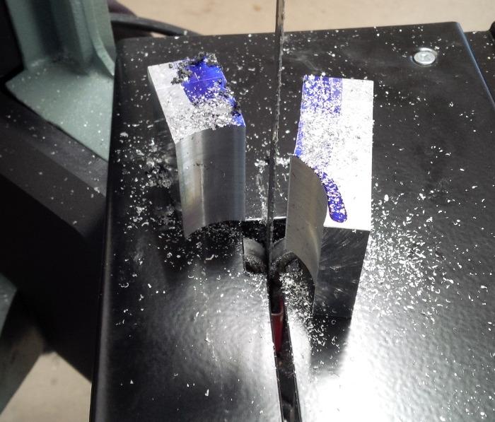
It isn't quick - not with the blade I have on it right now - but it works. And it is way nicer than using a Sawzall or manual hacksaw.
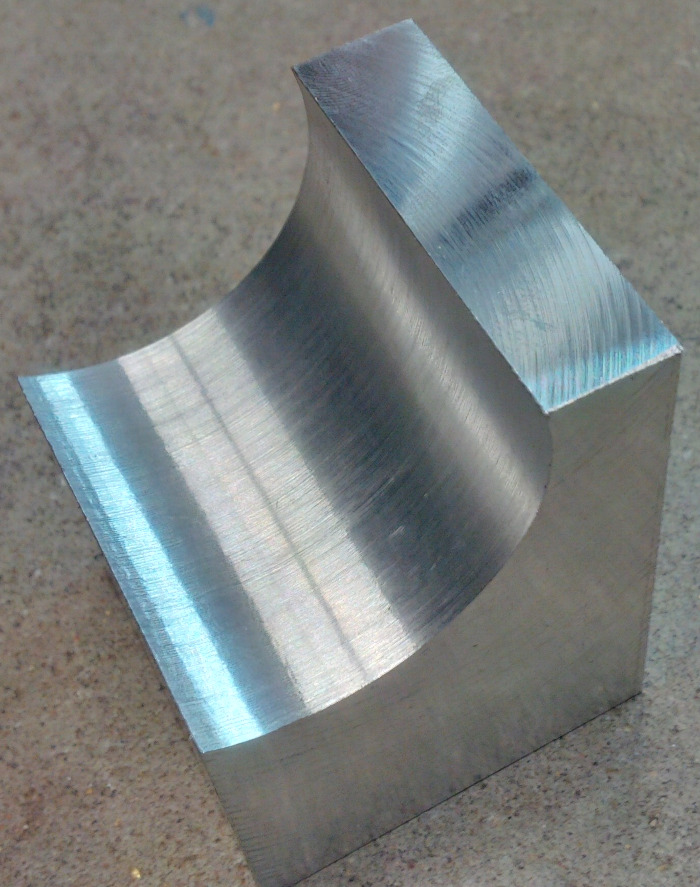
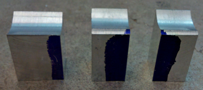
Of course, after cutting, we square it back up:
And now we have three standoffs roughed out.
Meanwhile, we can start to pie-piece the mandral bends and lay out the pipe:
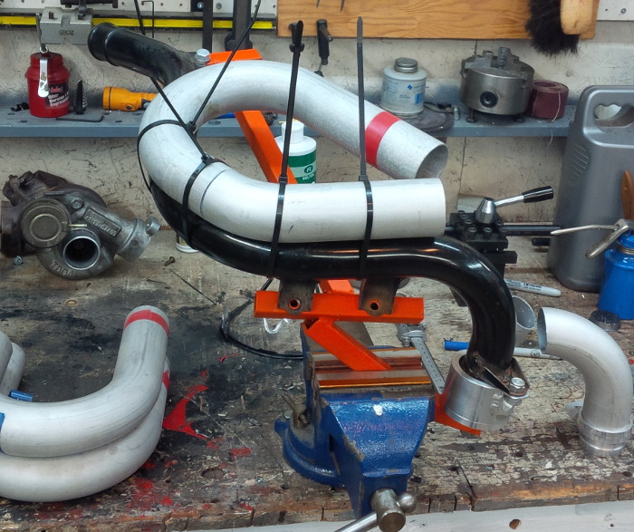
This just progresses along until we have a full pipe.
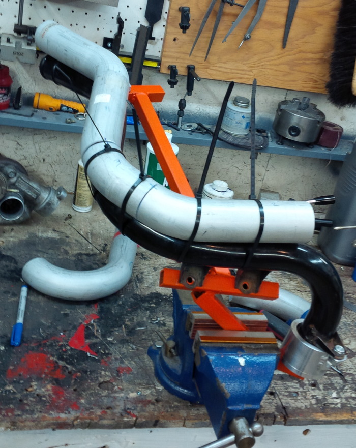
Until we finally have a mockup taped together for a test fit.
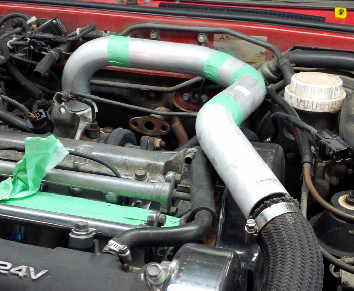
To be continued...
