Adding a MAP Sensor and BCS to an AEM EMS
One of the primary problems (from a tuning perspective at least) of the OEM Stealth / 300GT / DSM ECU is that it is MAF-only. Meaning that it only "understands" the amount of air entering the engine; not the current manifold (boost) pressure.
If you are an OEM, where you have thousands of hours to spend tuning the ECU calibration and where you control the configuration of the motor completely, this is not a big deal. Because while manifold pressure levels have important consequences for the amount of timing advance that can be run, the required air/fuel ratio, and fuel octane requirements (all of which vary with boost levels) all that time spent with the calibration means you get to know what boost levels are implied by what mass flow levels at what cell.
If maximum boost is controlled via external, mechanical means, the same is true for an AEM EMS in MAF mode. The AEM translates airflow into a Engine Load value and fueling and timing is varied according to this artificial number. It works.
But if you want to run boost control within the AEM EMS (and ultimately, if you ever intend for the car to operate in speed/density mode instead of MAF mode) the car will need a MAP sensor.
So then, we need a MAP sensor. Which one to use?
The old standby is the GM 3-bar sensor. Used by GM on Turbo Trans-Ams, Grand Nationals, and other late 80s to mid-90s turbo vehicles, I used this on the Talon quite successfully. It is a decent sensor, reliable and fairly cheap. But I chose not to use it, for the following reasons:
- It comes in 1, 2, and 3 bar versions, meaning unboosted (1 bar) 14.5 PSI max boost (2 bar) and 29 PSI max boost (3 bar). I intend to run somewhere between 16 and 18 PSI boost (historically the maximum amount possible on readily available premium pump gas) so a 2 bar is too small, and a 3 bar is too large; and
- Sensors are available now that combine the MAP function with the AIT function, meaning that only one sensor is needed to provide all the data necessary to convert the car to speed/density mode. They press right in to a drilled hole in the manifold so they make for a much neater installation.
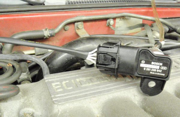
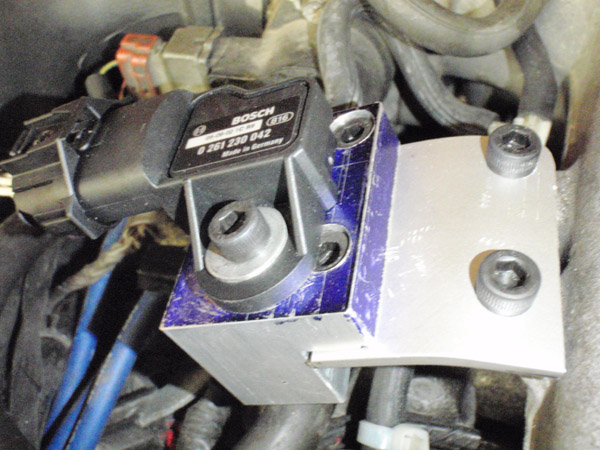
And as it happens, there is a 2.5 bar (21.7 PSI max boost) combo MAP/AIT sensor - the Bosch 0 261 230 042 sensor from a 2005 Chevy Cobalt SS.
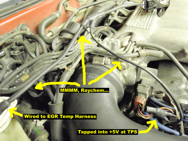
This picture shows the wiring harness fabricated up:
This is the sensor itself:
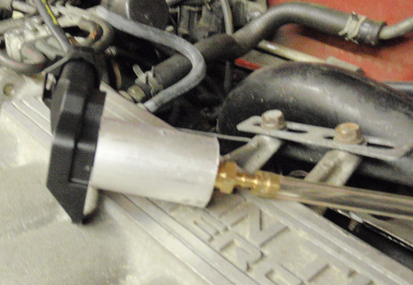
This is an adaptor I quickly fabbed up on the lathe so as to be able to test the sensor. Sensor plugs in one end, the other end is drilled 1/8" NPT for a hose barb.
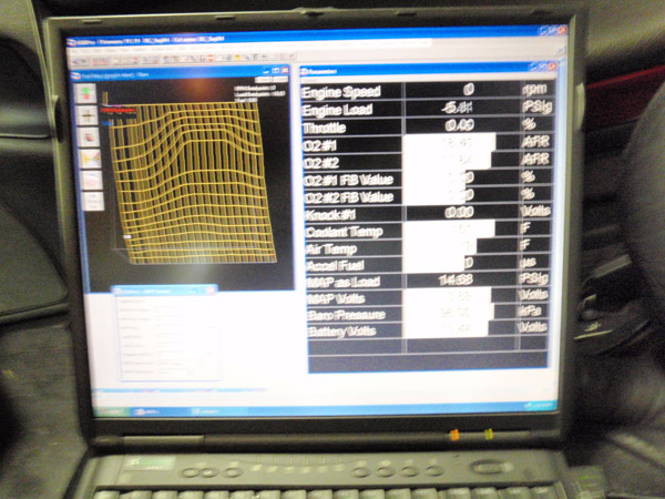
With the adaptor in place, I could apply pressure with a Mitivac:
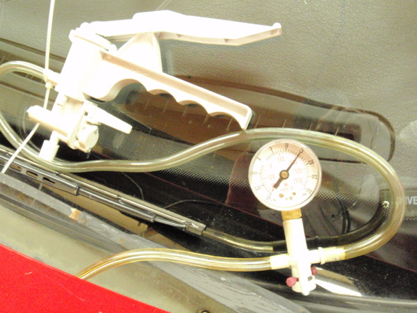
And read (and calibrate) the value on the AEM EMS.
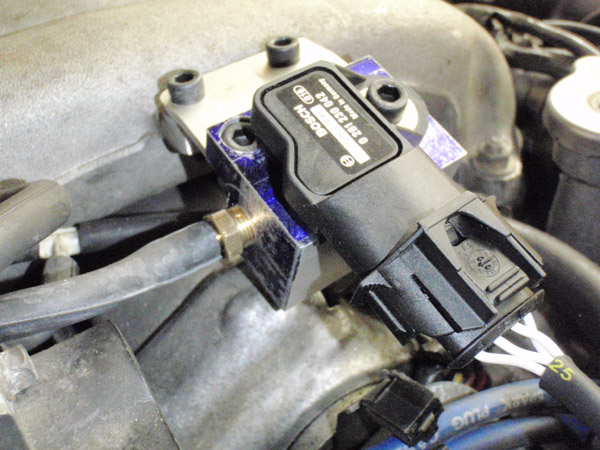
With that done, it was time to fab up a more permanent temporary adaptor. The final location will be a boss welded directly into the manifold plenum, so as to get the most accurate pressure and temperature values (and eliminate a hose). But until then, this adaptor will do fine, especially as I'm not reading the temperature value just yet.
It isn't the sleekest part I've ever made, but it gets the job done.
Enabling Boost Control with the AEM EMS
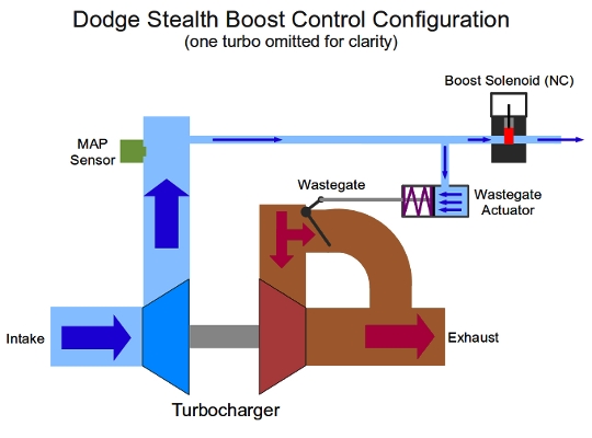
This is the layout of the boost control circuit for the Dodge Stealth and Mitsubishi 3000GT. This is a typical OEM-style control circuit for use with internal wastegates.
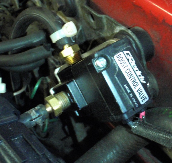
Rather than use the OEM boost control solenoid, I used the boost control solenoid from a Greddy PROFEC boost controller. I had been planning on using a MAC Valves solenoid (I even bought one) but a buddy of mine suggested that the PROFEC worked better, having better control authority and a more linear response than the MAC. I haven't tested the MAC solenoid (which is what AEM sells you as an AEM branded part) but the Greddy part works fine.
With all the hard parts mounted, it was time to configure the AEM EMS. By following the instructions HERE it was pretty straight forward to program the boost control functions. I set the car up using Vehicle Speed Based (VSS) boost control using a combination of the Boost WG Base Duty Map (set to 50% solenoid duty cycle in all on-boost cells greater than wastegate actuator spring pressure) and the Boost Target Comp table to set a hand-tuned offset to the base duty cycle based on the current target. (13.33 PSI in all speed cells)
Configured in this manner, the algorithm works like this:
- Look up the base solenoid duty cycle (based on Engine Speed and Engine Load) from the Boost WG Base Duty Map;
- Look up the current value for Boost Target (based on Vehicle Speed from the Boost Target Speed table;
- Look up the modifier to the base solenoid duty cycle (based on Boost Target) from the Boost Target Comp table;
- Apply the modifier to the base solenoid duty cycle to produce the final solenoid duty cycle; and
- Cycle the solenoid.
In this mode, the boost control solenoid acts as a fixed bleed from the wastegate actuator line. You can have a different bleed for different vehicle speeds, but there is no feedback loop in this control scheme; just a lookup for a duty cycle that corresponds to a particular boost target.
This control scheme works reasonably well.
But here is where things got interesting: while tuning on the dyno, we started overrunning the MAF (or at least its calibration) and so couldn't set the max boost to where we wanted it. But we did get dyno pulls where all that was changed from run to run was the fixed duty cycle on the solenoid, showing the effect of the boost controller when set to different bleed amounts:

That's not bad - but we can do better!
The AEM EMS has a pair of boost control feedback mechanisms. One is based on an algorithmic P-I (Proportional-Integral) feedback controller. The other is based on a user-calibrated Boost Error Duty table. This is an either-or decision; you cannot use both methods concurrently.
I chose to use the table-based Boost Error method rather than the P-I method.
With Boost Error Feedback turned on, the control algorithm looks like this:
- Look up the base solenoid duty cycle (based on Engine Speed and Engine Load) from the Boost WG Base Duty Map;
- Look up the current value for Boost Target (based on Vehicle Speed from the Boost Target Speed table;
- Look up the modifier to the base solenoid duty cycle (based on Boost Target) from the Boost Target Comp table;
- Apply the modifier to the base solenoid duty cycle to produce an intermediate solenoid duty cycle;
- Examine the MAP sensor (via the MAP As Load parameter) to determine the current boost level;
- Subtract the current boost level from the Boost Target value (looked up in Step 2) to produce the Boost Error value;
- Look up the boost error modifier to the intermediate solenoid duty cycle (based on Boost Error from the Boost Error Duty table;
- Apply the modifier to the intermediate duty cycle to produce the final solenoid duty cycle; and
- Cycle the solenoid.
Now we have a feedback loop, as the algorithm examines the current boost level and then applies a further correction to the solenoid duty cycle.
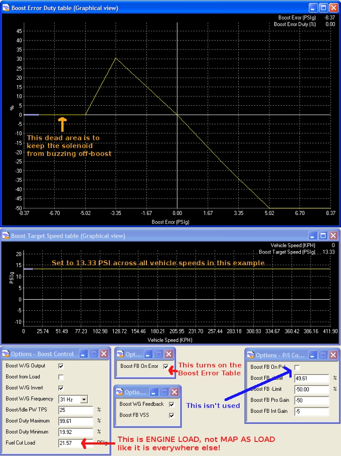
The AEMPro configuration screens to set this up look like this:
Here's the result: This is a comparison of a dyno pull using just VSS based control with no feedback (in red) against a road pull with Error Feedback turned on (in blue)
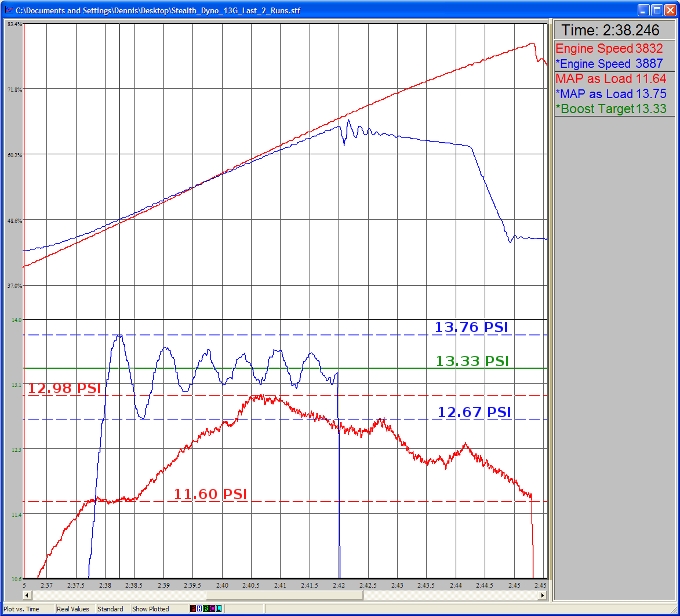
As you can see, the fixed-bleed boost level remains generally in the right area, but wanders all over the place. The feedback-enabled pull oscillates around the target value throughout the duration of the pull. There is an initial overshoot/undershoot cycle, but that quickly damps down to a +/- 0.2 PSI cycle - meaning that boost is never farther than 0.2 PSI away from the target. That's great!
And that's just my first cut at the error table. It should be possible to further reduce the amplitude of the initial overshoot/undershoot and the subsequent control oscillations, but I'm going to have to do some reading on feedback control theory first.
