CNC Cut Valve Cover Plate
The Stealth normally has a plate covering the spark plug holes on the forward head. A lot of people don't bother running one. I have a carbon fibre plate I bought somewhere... but the layup is kinda crappy and the fit horrible.
In the bigger priority picture, a replacement plate is pretty low down the list. But as building one is a tailor-made project for a CNC mill, and as I'm planning on doing a CNC desktop mill conversion project, working out how to build one via CAD / CAM is a good way to teach myself CAM and CNC manufacturing.
So first, we model the part in Solidworks and create a full-scale paper template. This is where the wife's scrapbook hobby comes in handy:
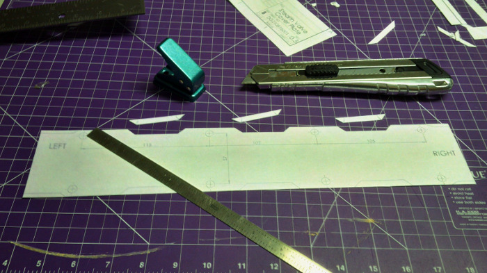
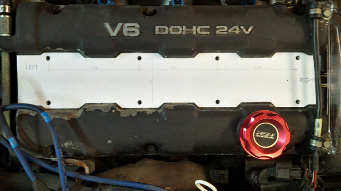
This took a few iterations until I was happy with the fit of the part. Note that there is probably enough size variation in the valve cover that a tight fit won't necessarily fit every car - there has to be enough room around the perimeter to allow for part variation.
With the template worked out, next we design the fixture that will hold the plate for machining. The idea here is to create a part that the mill vice can hold firmly and squarely, and which physically references the vice so the fixture can be removed and installed but always occupy the same spot on the table. The part, in turn, physically references the fixture so that the relationship between the fixture and the part is always the same.
We also want to try and minimize the number of setups needed to make the part. Every setup change is an opportunity for error and time that could be spent making chips.
So the operations we need to make our part are:
- Face the top side smooth and flat;
- Cut the bolt holes that hold the plate to the valve cover;
- Cut out the outside profile of the plate itself; and
- Cut out any decorative engraving we might want to do.
For Step 1, we have to clamp a piece of bar stock to the fixture. That means that the clamps must be far enough apart to the face mill can reach between them (nothing good comes from a face mill meeting a clamp). That, in turn, means that the bar stock must be wide enough to support being milled and clamped.
When Step 2 is finished, we will have bolt holes that we can use to secure the part to the fixture. That means we could get rid of the clamps if we wanted. But Step 3 separates the part from the bar stock, and we can't have it coming loose while still being worked on. The usual answer is to not machine the outer profile all the way through the bar stock, and then breaking the part loose afterwards. But that means a manual deburring step which is annoying and time consuming. So instead, we can put a stop in the program after Step 2 and bolt down the part to the fixture. Then, with the part and the waste stock both secured, we can machine all the way through and nothing will move around.
Step 4 could be done before Step 3 - but we want to anodize the part black, and then cut out the lettering so it shows up better. That means we need to be able to secure the part in the same place on the fixture without having the waste stock in place - another argument for bolt holes in the fixture.
All this means the fixture must have:
- A place for the vice to grab it;
- A shoulder to locate the fixture Y location to the vice;
- A pocket for the bar stock to fit into, that references the bar stock in X and Y;
- Bolt holes in the same places, relative to the part pocket, that the bolt holes in the valve cover occupy; and
- Bolt holes for the clamps, spaced to hold the part securely, but not interfere with the cutting tools.
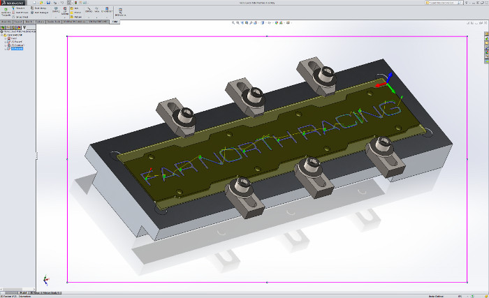
Here is what that looks like:
The next part is the generation of tool paths and G code for the machine to chew on. It sure would be nice to do this inside of Solidworks, rather than having to go to MasterCAM or LinuxCAM or whatever...
We can! Enter HSMXpress, which is a CAM add-in for Solidworks. This is a stripped-down version of the full HSMWorks package that is limited to just 4 axis - and it is FREE - and it is AWESOME!
With HSMXpress, you model your part and fixture, convert them to a Solidworks assembly, and then follow some easy steps to identify the part being manufactured. The look and feel is exactly the same as Solidworks, the integration is seamless, and it is quick!
Here is the result:
So what you are seeing:
- A face mill decks the part;
- A 1/8" end mill clears out the bolt holes; (at this point I would pause the operation and screw the part down using these holes)
- That same end mill cuts the outer profile; (at this point the part would be pulled and sent for anodizing) and
- A 2mm end mill cuts the lettering.
The really cool part is that, with the fixture built, making a batch of these is almost as fast as making one. That means it is possible to cut a bunch of them, send them out for anodizing, and then cut custom lettering into each one. Personalized valve cover plates....
To be continued....
