Revised MAP Sensor Adaptor
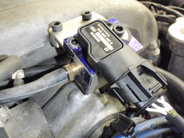
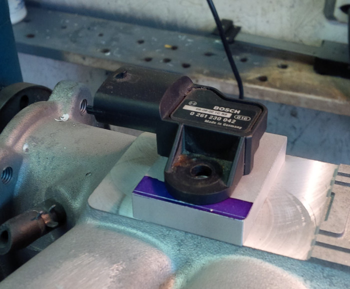
So way back when, I fabricated this simple block to house the Bosch MAP/AIT sensor and provide a boost pressure reference:
And then life got in the way. A move out East to Gagetown, three years at the Armour School with zero free time... the Stealth has been lying fallow for quite some time. Happily, I've been able to recover some free time and a whole hockey-sock of Stealth projects are on the go.
The adaptor block for fitting the Bosch sensor to the manifold is the first in the hopper.
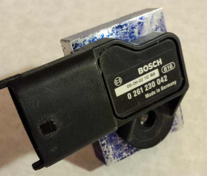
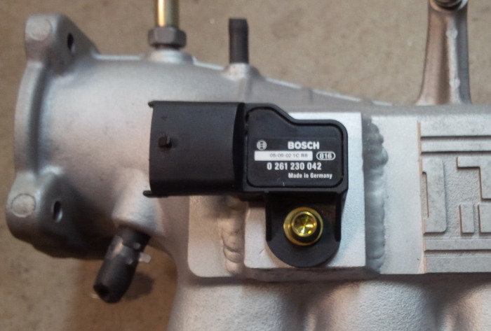
This sensor is designed to fit on top of the manifold plenum. A probe fits down inside to provide the intake air temperature measurement, while a passage inside the bore provides the boos pressure reference. The assembly seals on a 12mm bore via an o-ring, and is held in place by a single 6mm socket head cap screw.
It is a very clean and compact sensor, but the catch is that 12mm bore. The OEM manifold is not thick enough to be able to provide that bore - nor is it thick enough to house the hold-down screw. So what we need is an adaptor plate that provides enough depth to establish the sealing bore, plus house the hold down screw without penetrating into the manifold plenum and requiring sealing the threads somehow.
This is the answer:"
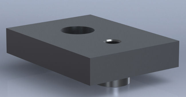
The clever bit is the boss just below the screw hole. Aside from allowing the screw hole to be deep enough to not break into the plenum, it serves as a locator pin to assist in the welding of the plate to the manifold.
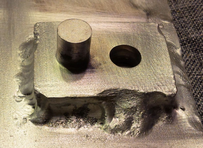
The first order of business was to mill up a prototype:
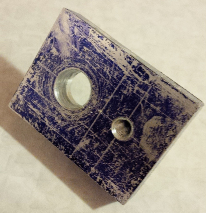
Figuring out how to do the underside was tricky, as I don't have a CNC mill (yet) nor a 4-jaw chuck for the lathe. By screwing an arbor to the hold-down screw hole, I was able to rotate the part around the screw-hole axis and round out the boss after roughing it out in the mill. Worked pretty well!
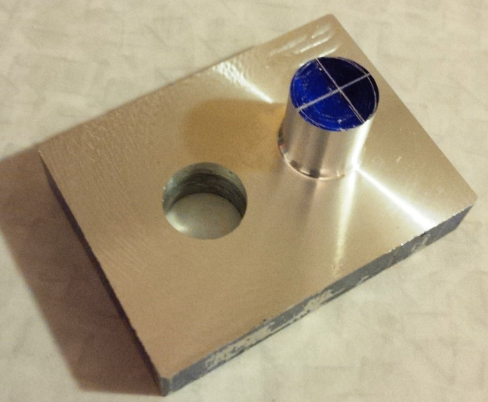
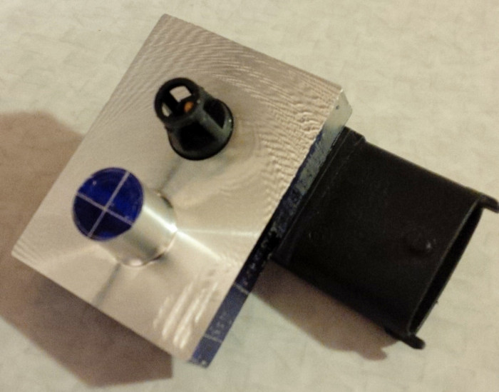
Here is the sensor snugged into the bore. That bore was drilled slightly undersize and then reamed out with a hand reamer. The production version wasn't reamed until after the weld was done.
Here's the more important view, showing the sensor probe just peeking through the adapter plate. The boss got cut down substancially for the production version.
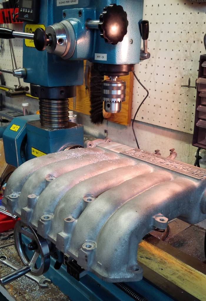
Next, the manifold needed ti be milled flat. An angle plate bolted to the table and the throttle body bolted to the angle plate produced a nice rigid setup (as rigid as my mill ever gets at least). I milled off the raised "ECU Multi" lettering on the casting so as to not reduce the casting wall thickness at all. This also exposed nice fresh metal for the weld.
Next came drilling the two mount holes - one for the sensor probe, and one for the boss.
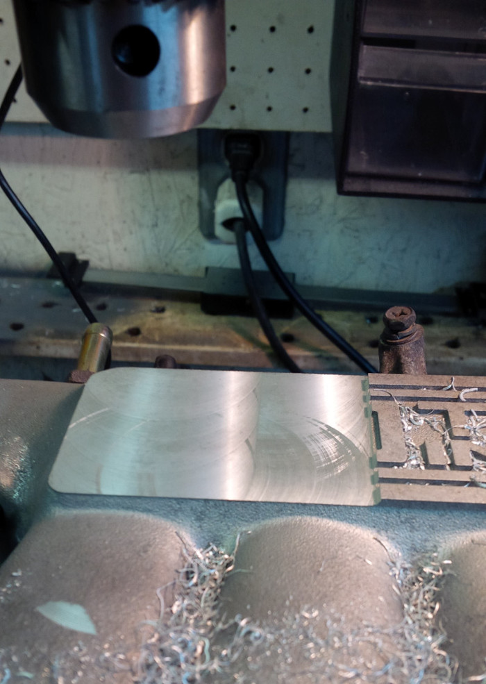
A test fit revealed that a little bit needed to be trimmed off. The scribed line shows the cut needed.
And with that done, we were ready to weld.
...at least, in theory we were ready to weld - because first I had to learn how to weld aluminum.
First attempts were less than pretty....
But with time - and argon - improvements were made.
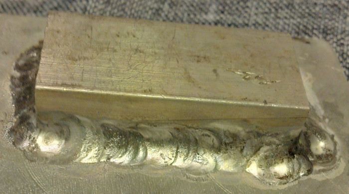
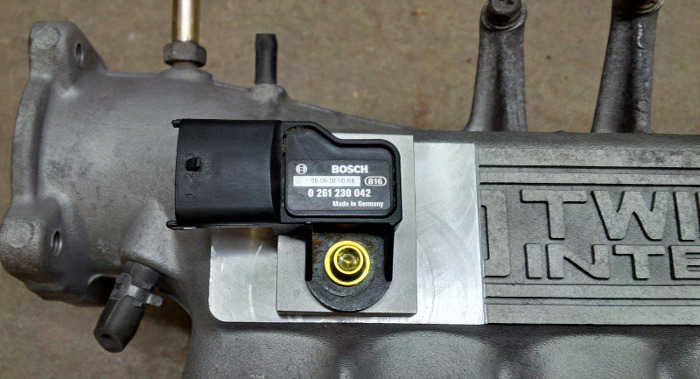
Eventually I got brave enough to tackle the real thing - and it turned out OK.
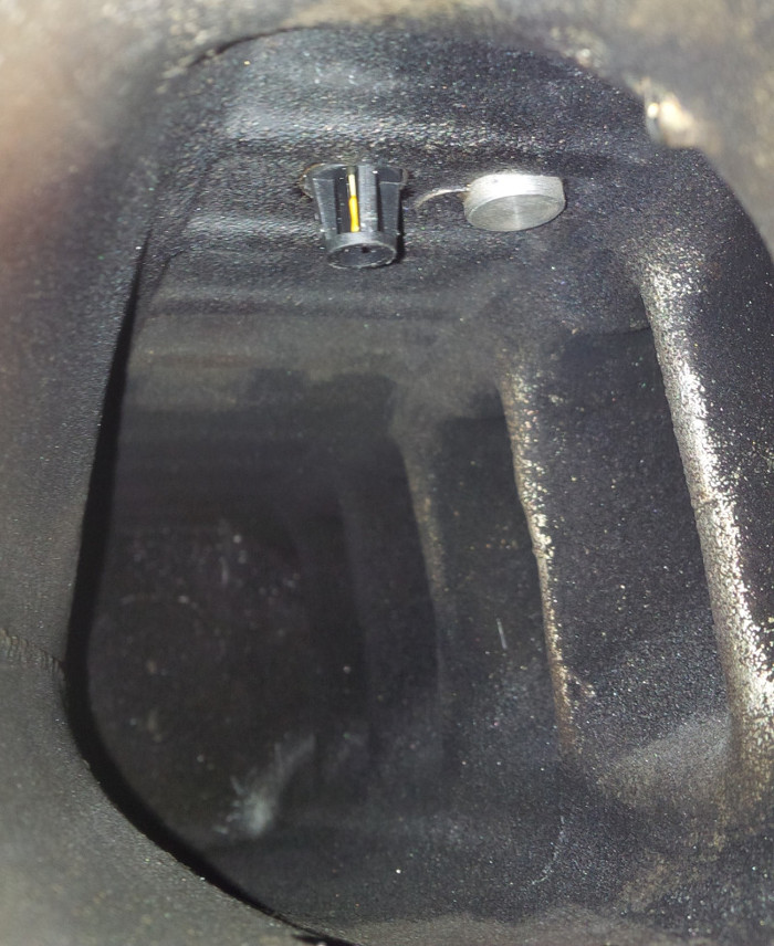
And here is what it looks like inside the manifold. The sensor plug extends nicely into the plenum, and the boss doesn't stick out enough to hurt airflow through the manifold.
Next we test fit in the car - and whoops! We have a clearance problem. The sensor hits the hood...
To be continued...
