Programming Mitsubishi EGR with the AEM EMS
Although the AEM EMS is marketed as a "plug and play" system, there are quite a few functions that the OEM ECU provides that the AEM EMS does not.
Some of these functions are directly supported by the AEM software - for example, the Charcoal Evap Canister Purge - but are not enabled by default, nor are they configured. Some functions are not wired in correctly - why, for example, is the Active Exhaust Switch not set to a switch input, where it could be useful? And some functions can only be enabled with a bit of hacking and magic.
EGR is one of these.
EGR is "Exhaust Gas Recirculation" and it provides two functions:
- The reduction of oxides of nitrogen (NOx) production at part-throttle cruise; and
- A fuel economy increase through reduction of pumping losses.
In both cases, under certain conditions, a valve is opened that allows some burnt exhaust gas to be recirculated back into the intake charge. Because this gas is chemically inert (all that could be reacted did so when it passed through the engine the first time - at least in theory) but still has volume, it serves to both cool the exhaust temperature (this is what reduces NOx production) and to require a larger throttle opening to produce the same power level (this is the fuel economy improvement portion)
The fuel economy aspect deserves a closer look:
It doesn't take a whole lot of power to keep the car moving at a constant speed (cruise). Accordingly, the throttle angle is fairly small. This creates a partial vacuum in the intake manifold, because the engine is trying to draw air through a very small hole. Much like trying to breath through a gas mask, this causes the engine to work harder to draw that vacuum. This extra work is called "pumping losses".
By allowing some exhaust back into the intake manifold, some of the space in the manifold is taken up by inert gas. Accordingly, in order to keep the same power production, the throttle must be opened wider, to produce the same net amount of reactive oxygen in the manifold. The amount of fuel being burnt is still the same - the power produced in both with-EGR and no-EGR cases is the same amount. But because the throttle is opened wider in the with-EGR case, pumping losses are reduced, and that means better fuel economy.
How much better is open to some debate, and appears to be tough to work out from first principles. I've found sources claiming "up to 8%" which seems a reasonable guess. Assuming EPA highway mileage of 21 MPG (about what I have been seeing on my car, more or less) that works out to an improvement of about 2 MPG.
I routinely drive from Windsor to Toronto and back, a round trip distance of roughly 500 miles. At 21 MPG, that's 23.8 gallons of fuel. At 23 MPG, that's 21.7 gallons. Converted to litres, that's 90.2l and 82.3l respectively. Sunoco 94 octane premium fuel is $1.40 a litre right now, so that's $126.21 vs $115.22 - a $11.00 difference. That's a noticeable improvement, just for enabling a software function using hardware that is already there.
On the emissions front, I'm a big fan of keeping real street cars emissions legal. Part of this is forced on me; Ontario does smog checks on cars, and the car must pass in order to be driven. The Stealth has a loophole on the NOx front, because NOx production must be tested under load, and the Ontario Drive Clean equipment cannot handle AWD cars. Accordingly, the Stealth gets a pass for NOx, and the EGR system has no real effect on CO or hydrocarbon emissions (tested at idle). The EGR system need not be active to pass smog in Ontario. But that doesn't mean I have licence to spit out all the NOx I want.
Those of us who modify cars need to be able to place nicely with others when it comes to things like pollution controls. For a race car - sure, open season. Winning comes first and if the rules don't require you to run smog equipment, it makes sense to remove it. But as far as I'm concerned, no street car should be operated without all the applicable emissions controls in place and fully operational.
How the OEM EGR Control Strategy Works
This is the emissions control system diagram for the Stealth. I have removed the wastegate controls, fuel pressure control, and BOV from this diagram to simply things (none of those subsystems affect EGR)
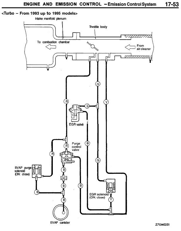
Perhaps the most important aspect of that diagram is that the vacuum source for the EGR valve is PORTED, meaning that when the throttle is fully closed, the "vacuum" port in the throttle body is upstream of the throttle blade. It thus takes some degree of throttle application before the port is on the downstream side of the port and "sees" vacuum.
It is also important to notice that the EGR valve isn't exactly "vacuum" operated. The actuator is a differential pressure actuator, and the backside of the diaphragm is referenced to the pressure upstream of the throttle. This allows the valve to account for flow losses in the air filter, intercoolers, and what have you, rather than relying on an absolute manifold pressure to open or close the valve.
An electric solenoid, ECU controlled, is plumbed into the system - and this solenoid controls the valve, like so:
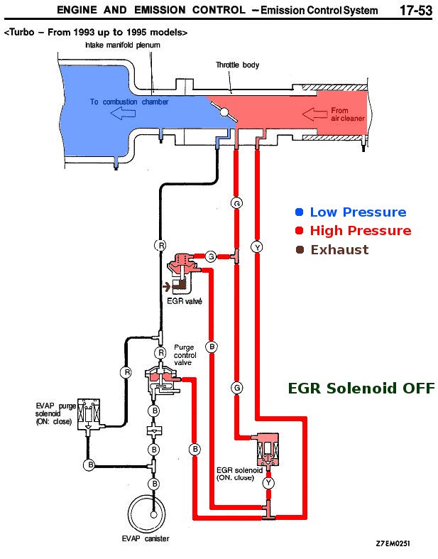
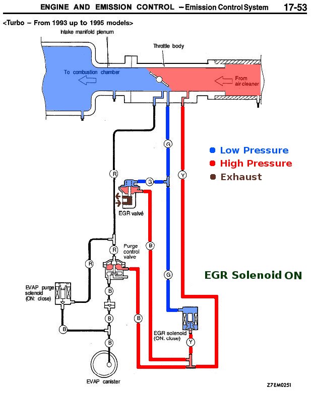
So the following conditions must be met in order to open the EGR valve and allow exhaust to flow into the intake:
- The throttle must be opened wide enough to cover the port in the throttle body;
- The pressure difference between the EGR port and the reference port must be greater than the spring pressure in the valve (9.1 in/Hg or 4.5 PSI); and
- The EGR solenoid must be energized.
Now it remains to determine what the OEM ECU solenoid control strategy is:
Thanks to Jeff V. who successfully reverse-engineered the OEM ECU code, we discovered the following things:
- There is a 3D EGR map and a 2D EGR temperature compensation table;
- The 3D map has Engine RPM on the X axis and Engine Load on the Y axis. Cell values are solenoid duty cycles;
- The 2D table has Coolant Temp on the X axis. Cell values are multipliers to duty cycle.
The algorithm is very simple:
- Look up the duty cycle from the 3D map using RPM and Load,
- Look up the temperature multiplier from the 2D table using Coolant Temp,
- Multiply the two values together and apply that duty cycle to the solenoid.
And here are the values:
| EGR Temperature Comp | |||||||||||
| Engine coolant temp (°C) | -9 | -5 | 27 | 59 | 91 | 123 | 155 | 187 | |||
| Multiplier (%) | 100 | 100 | 0 | 0 | 0 | 0 | 0 | 0 | |||
| Base EGR Duty cycle (%) | 750 | 1000 | 1250 | 1500 | 1750 | 2000 | 2250 | 2500 | 3000 | 4000 | |
| RPM (X) | 0.187 | 0 | 0 | 0 | 0 | 0 | 0 | 0 | 0 | 0 | 0 |
| Air mass in g/rev (Y) | 0.281 | 0 | 0 | 0 | 0 | 0 | 0 | 0 | 0 | 0 | 0 |
| 0.375 | 0 | 100 | 100 | 100 | 100 | 100 | 95 | 91 | 62 | 35 | |
| 0.469 | 0 | 100 | 100 | 100 | 100 | 84 | 75 | 66 | 50 | 28 | |
| 0.562 | 0 | 100 | 100 | 100 | 100 | 67 | 50 | 41 | 37 | 21 | |
| 0.656 | 0 | 100 | 100 | 90 | 84 | 65 | 53 | 45 | 41 | 21 | |
| 0.750 | 0 | 100 | 100 | 80 | 68 | 62 | 55 | 48 | 45 | 20 | |
| 0.844 | 0 | 100 | 100 | 90 | 84 | 81 | 77 | 74 | 54 | 24 | |
| 0.937 | 0 | 100 | 100 | 100 | 100 | 100 | 100 | 100 | 62 | 28 | |
| 1.125 | 0 | 100 | 100 | 100 | 100 | 100 | 100 | 100 | 78 | 47 | |
| 1.312 | 0 | 100 | 100 | 100 | 100 | 100 | 100 | 100 | 75 | 69 | |
| 1.500 | 0 | 100 | 100 | 100 | 100 | 100 | 100 | 100 | 75 | 69 |
From this we see that:
- EGR is switched off at cold temps (JEFF - note that this reads wrong based on table values - shouldn't they be inverted?)
- EGR is switched off at low loads and at idle
- EGR is switched off by 4000 RPM
- EGR is switched off at loads over 1.5 g/rev
- EGR is mostly tapered down from full EGR at 1000 RPM to 0 EGR at greater than 4000 RPM, although there is a bias towards more EGR at the higher loads
Translating the OEM EGR Calibration to the AEM EMS
Now that we know how the OEM ECU controls the strategy, it is now time to translate that strategy to the AEM EMS.
To do this properly, we need a 3D map and a 2D table capable of controlling a duty cycle output.
The Plug and Play wiring setup puts the EGR solenoid on LS4 (NOTE!! The manual is in error!! It claims the EGR solenoid is on Injector8 and the Evap Purge solenoid is on LS4, but they are reversed!)
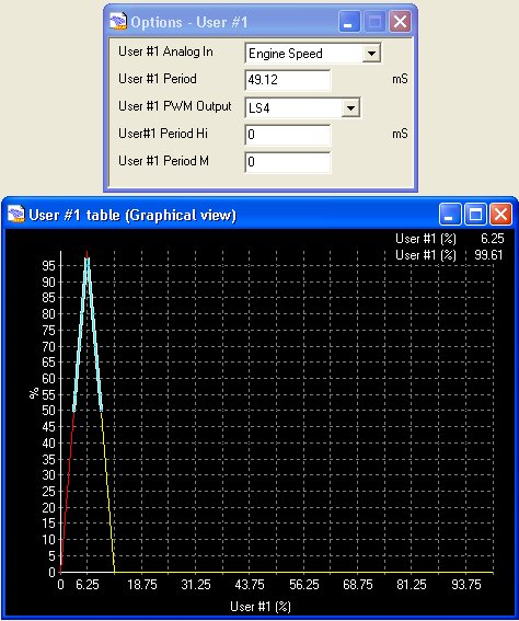
User PW#1 Method
The AEM has a user-definable table for controlling an arbitrary pulsewidth (PW) solenoid called the User PW #1 table. This table can be instructed to point at any PW output in the AEM, and the X axis can be any AEM input. By assigning the output to LS4 and the input to Engine Speed, we can provide a rough approximation of the 3D map. And by setting an output function to disable LS4 until coolant temp reaches 27C, we can get the same effect as the OEM temp compensation table.
There are a couple of drawbacks to this method:
- There is no Load sensitivity to this method, which means we cannot match the OEM load axis calibration, and we are dependant on the mechanical aspects of the system to disable EGR on boost; and
- The User PW#1 is NOT "breakpoint aware" - meaning that it doesn't know about the RPM breakpoints used to scale all other RPM-dependant tables. Instead, the scaling on the RPM axis is fairly wide; meaning we get a cell at about 1500 RPM and another cell at about 4200 RPM, and that's it.
This is what the configuration for this method looks like:
VVT Method
The AEM also has a pair of strategies designed to control Variable Valve Timing (VVT) setups like MiVEC. This provides a 3D load vs RPM map, and can control Injector9 or Injector10.
The cells in the VVT map are values from 0-80 (intended to be camshaft degrees) but there is a second table that maps "camshaft degrees" to "duty cycle" - so by populating this table with a linearly scaled 0-100% DC over the 0-80 "camshaft degrees", you get, effectively, a "normal" 3D map.
With this enabled, plus an output function set for the temperature control, the OEM EGR control strategy can be duplicated EXACTLY.
There are two drawbacks to this method:
- The VVT tables cannot be set in software to control LS4, which is the default PnP wiring for the EGR solenoid. Accordingly, the pin must be moved in the wiring harness, which is an enormous pain in the ass; and
- As of yet, there does not exist an algorithm to convert the OEM g/rev load scaling to the AEM MAF Calibration Load Scaling meaning that the Y axis of the OEM scale are unknown values. This is being actively worked on and I hope to have a solution soon.
...to be continued.
